If you need to inquire or purchase ,please send the product models to my email or call me directly .
Contact detail:
Xiamen Xiongba E-commerce Co., Ltd
Mobile/ WeChat/ WhatsApp:+86 13365909307
E-mail: dcsplcsales@gmail.com
Contact: Simon Zhang
Website: https://www.dcsplcsystem.com
Address: Unit 2008, Chuangxiang Center, No. 1733, Luling Road, Siming District, Xiamen, Fujian

The on-site debugging work mainly involves checking and using the system software, and conducting configuration confirmation and functional testing on the application software.
1. Inspection before power on
The cable insulation resistance meets the requirements (greater than 5M ohms). Check the cable insulation resistance test records and conduct spot checks and measurements if necessary.
Verify that all power lines, signal lines, and communication buses are connected correctly.
The models and positions of the cards, adapters, and their interfaces in the control station, operation console, engineer station, and other frames are correct and correct.
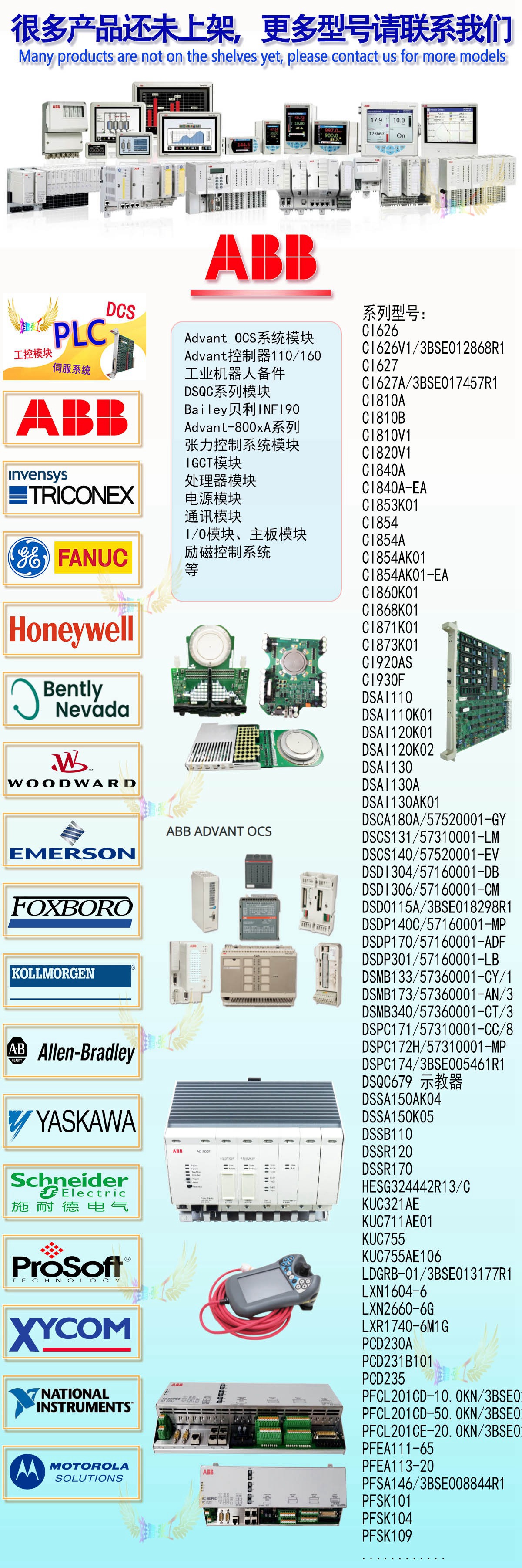
KUC711AE 3BHB004661R0001
KUC711AE
3BHB004661R0001
07KT98C GJR5253100R028
07KT98C
GJR5253100R028
07KT97 GJR5253000R4270
07KT97
GJR5253000R4270
KUC711AE01 3BHB004661R0001
KUC711AE01
07KT98 GJR5253100R4278
3HNM07686-1
3HNM07485-1/07
PFTL101A 1.0KN 3BSE004166R1
PFTL101A 1.0KN
3BSE004166R1
PFTL101B 5.0KN 3BSE004191R1
PFTL101B 5.0KN
3BSE004191R1
5SHX1445H0002 3BHL000387P0101
5SHX1445H0002
3BHL000387P0101
TP852 3BSC950263R1
TP852
3BSC950263R1
UNS2881b-PV1 3BHE009319R0001
UNS2881b-PV1
3BHE009319R0001
CI855K01 3BSE018106R1
CI855K01
The preset knob positions for each card are correct.
The power switch on the power unit and card is in the "OFF" position, and all fuses are intact.
All connecting screws inside the cabinet should be firm and not loose.
Grounding system grounding resistance test:
Remove the "MG" and "CG" grounding busbars from the control room grounding plate, and use a grounding resistance tester to measure the basic grounding resistance separately, which should meet the design requirements (less than 10 ohms).
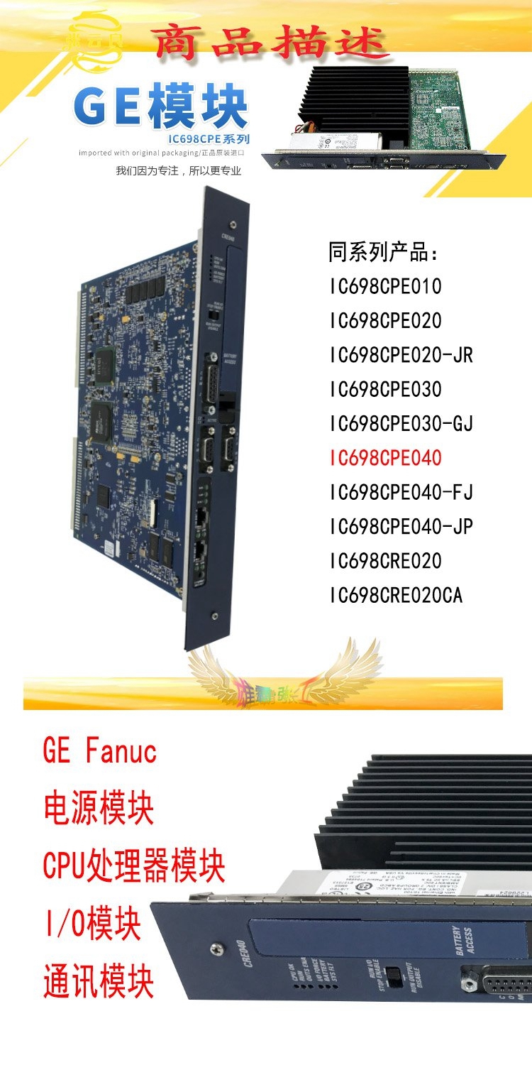
AV94A HESG440940R11
HESG216791/A
UNS2880b-PV2 3BHE014967R0002
UNS2880b-PV2
3BHE014967R0002
UNS0887A-P 3BHE008128R0001
UNS0887A-P
3BHE008128R0001
UNS2882A 3BHE003855R0001
UNS2882A
3BHE003855R0001
UNS4881bV4 3BHE009949R0004
UNS4881bV4
3BHE009949R0004
216EA62 1MRB150083R1/F
216NG62A
Use a multimeter to check if the grounding busbar of each cabinet is connected to the "MG" and "CG" grounding plates.
The insulation resistance between "MG" and "CG" measured should meet the requirements of GBJ93-86 specification (greater than 5M ohms).
UPS power supply test:
Check that both the power panel and the power switch are in the "OFF" position.
The UPS will be put into operation by electrical personnel, and the voltage measured before being sent to the main power switch of the instrument power panel should be 220VAC ± 10% and 50Hz ± 2%.
UPS uninterrupted test shall be conducted by electrical personnel. After fully loaded operation, repeat this test, and the battery power supply time should not be less than 30 minutes
HESG216791/A
UNS2880b-PV2 3BHE014967R0002
UNS2880b-PV2
3BHE014967R0002
UNS0887A-P 3BHE008128R0001
UNS0887A-P
3BHE008128R0001
UNS2882A 3BHE003855R0001
UNS2882A
3BHE003855R0001
UNS4881bV4 3BHE009949R0004
UNS4881bV4
3BHE009949R0004
216EA62 1MRB150083R1/F
216NG62A
HESG441634R1/K
HESG216876
216DB61 HESG324063R100/J
HESG324063R100/J
PPA322B HIEE300016R2 HIEE400235R1
PPA322B
HIEE300016R2
HIEE400235R1
3BHB013085R0001
3BHE009681R0101
GVC750BE101
UNS0881a-PV1 3BHB006338R0001
UNS0881a-PV1
3BHB006338R0001
CI854 3BSE025347R1
CI854
3BSE025347R1
PM783F 3BDH000364R0002
PM783F
3BDH000364R0002
PFTL101BE 2.0KN 3BSE004214R1
PFTL101BE 2.0KN
3BSE004214R1
LXN1604-6 3BHL000986P7000
LXN1604-6
3BHL000986P7000
UFC760BE43 3BHE004573R0043

Perform the following power-on tests on each cabinet and operating console one by one:
Place the cabinet power switch inside the power panel in the "ON" position and use a digital multimeter to check the voltage before the main power switch of the cabinet, which should be 220 ± 22VAC.
Confirm that all cards in the cabinet (excluding power cards) have been unplugged from the card holder, and then place the main power switch, power unit, and power switch on the power card in the cabinet in sequence to "ON". Use a digital voltmeter to measure the DC voltage output, which should meet the manufacturer's instructions (5.1 ± 0.02V, -12 ± 0.3V, 12 ± 0.3V, 24 VDC). If it exceeds the allowable deviation range, make adjustments.
Perform a manual switching test with dual power sources.
Connect the power to each nested fan, signal converter fan, hard drive fan, cabinet top, door fan, etc., and check that each fan is operating normally.
Check if the power alarm circuit is working.
UNS0119A-PV101
GDD360C
UFC911B110
UCD240A101
SC520 3BSE003816R1
SC520
3BSE003816R1
MB510 3BSE002540R1
MB510
3BSE002540R1
SR511 3BSE000863R1
SR511
3BSE000863R1
CS513 3BSE000435R1
CS513
3BSE000435R1
SC520M 3BSE016237R1
SC520M
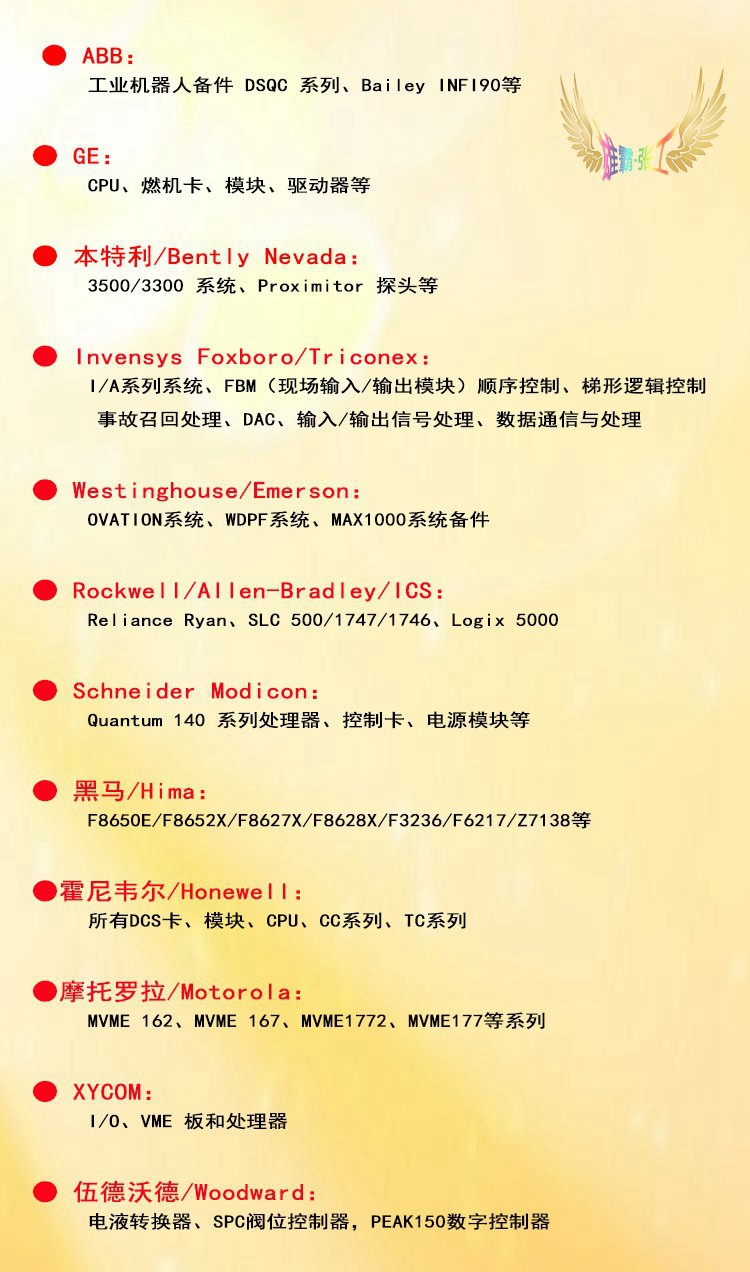
RF533
3BSE014227R1
PPD115A102
3BHE017628R0102
DSDP140B 57160001-ACX
DSDP140B
57160001-ACX
SCYC51010
58052515G
NMTU-21C
3BSE017429R1
NBIO-21CU
3BSE017427R1
3BHB002916R0001
UFC721AE
T-1521Z
R-2521Z
751010R0815
75018476043/1/1VC1T0374A00R
CP450-T-ETH
ACS-CP-C
DSQC355A
IMASI23
V4550220-0100
TU810V1
NTAC-02
INSEM01
PM803F
DO810

